


|
Model:GPE48150F
Power System of High Performance and High Reliability
GPE48150F Embedded Power System
Input:90~280Vac; Output: -42~-58Vdc;
Application
♦Small scale program controlled exchanger
♦ Access network
♦Transmission equipment
♦ Mobile communication
♦ Satellite communication ground station
♦ Microwave communication
Main features
♦Adoption of active power factor compensation technology with factor >0.98
♦Wide operating range of AC input voltage: 90~280Vac
♦Operating temperature range:-25°C~+55°C
♦Zero current/voltage switching tech with high efficiency ≥91%
♦Lifecycle of battery prolonged by perfect battery management, including electrical charge/discharge management, battery temperature compensation, battery capacity test, reversal connection proof protection, low voltage protection etc.
♦Hot-swappable
♦Input over/under voltage protection
♦Output over voltage protection
♦Output over current protection
♦Output short circuit protection
♦Auto current sharing, parallel operation
♦Embedded mounted
♦Perfect surge protection function 20KA(8/20 US)
The GPE48150F embedded power system consists of the power distribution frame, monitoring module and rectifier module. The whole system is of high reliability and performance, and can be operated through PC software.
1. General
1.1 System configuration
The system consists of power distribution unit, rectifier module (from 1 set, up to 5 sets
) and 1 monitoring module. The configuration is optional, as following table:
1.2 Operating principle
AC power is first input AC-INPUT MCB and then feed into the rectifier module after lightning proof and filtering. AC-INPUT acts as protection to over load and short circuit to AC power. LOAD1-, LOAD2-, LOAD3-, LOAD4- are connected with two load down contactor KM1, KM2. The user’s battery is connected to the DC output side through MCB BAT and KM2, and the circuit breaker provides disconnection control, over-load and short-circuit protection to the battery.
Under normal conditions, every parameter of rectifier modules and power distribution unit are all under control of the monitoring module, operating according to the pre-set parameter or user’s commands. If AC mains faults, the battery will power to the system. With the battery discharge, the terminal voltage of the battery starts to descend. When battery voltage is under -47V±0.5V, the monitoring module sends DC under voltage alarm signal and when battery voltage is under -46.0V±0.5V (adjustable), the monitoring module will control the contactor KM1 to cut off LOAD3 and LOAD4 and retains power to LOAD1 and LOAD2 . If battery voltage drops to -43.0V±0.5V (adjustable), the monitoring module will control the contactor KM2 to cut off output of LOAD1 and LOAD2, then the power system will stop working. If the external AC mains recovers, the system will normally work again. (All above monitoring data are system default values and can be reset by user).
Except for battery over-discharge protection, battery or load over-temperature protection is prohibitive under default, users can send command to activate or inactivate according to the demanding.
1.3 System Properties
2. Installation
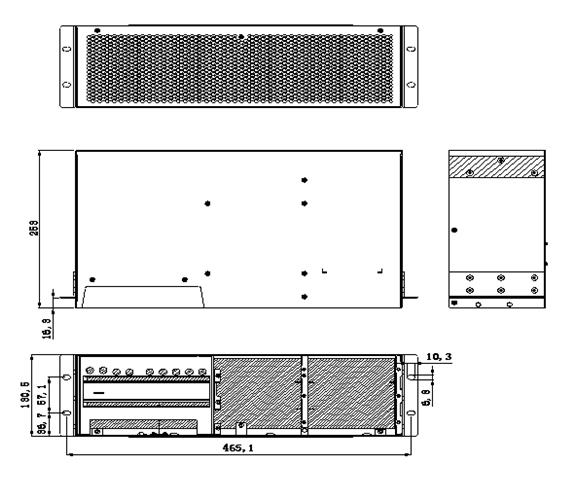
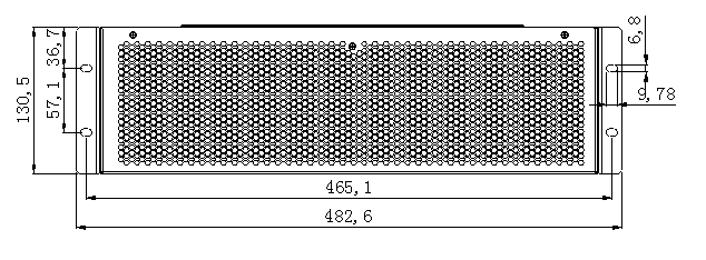
2.1 Dimensions diagram
2.2 GPE48150F Installation
GPE48150F is embedded power system. First insert GPE48150F to the specified location inside the cabinet till the system is well fixed. Keep the 4 fixing holes on the bracket in line with those on the cabinet and then screw up 4 pcs M4 cross rounded head screws (including spring washer and flat washer). Finally complete the installation after tightening the screw.
Note: The cabinet shall be provided by the user.
3. Electric connection
Chassis connects with external electric through system interface board. As shown in figure below:
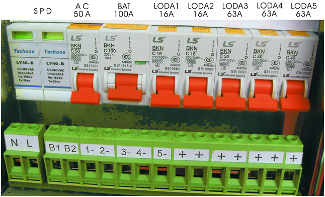
Wiring Terminal Instruction:
(1) N is null line; L is live line;
(2) B1,B2 are battery cathodes;
(3) 1-,2-,3-,4-,5- are load cathodes;
(4) + is load anode.
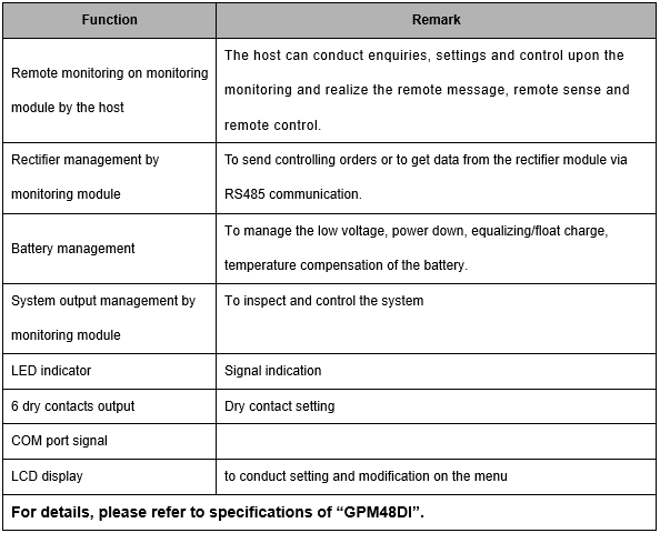
4. GPM48DI Monitoring Module
4.1 Functions of monitoring module
4.2 Installation of monitoring module
Handles on panel of monitoring module are equipped. When inserting monitoring module into the main cabinet, the operator shall clutch the handle with one hand while holding it with the other hand. Slowly push the module into its slot until the connection terminal on back of the module are inserted into corresponding socket of system bar in the main cabinet. Finally, finish the installation by firmly fixing the screw on the panel to the main cabinet. When removing module from the main cabinet, first screw off the screw on panel, then slowly remove the module from its slot while clutching the handle.
5. GPR4830A1 Rectifier Module
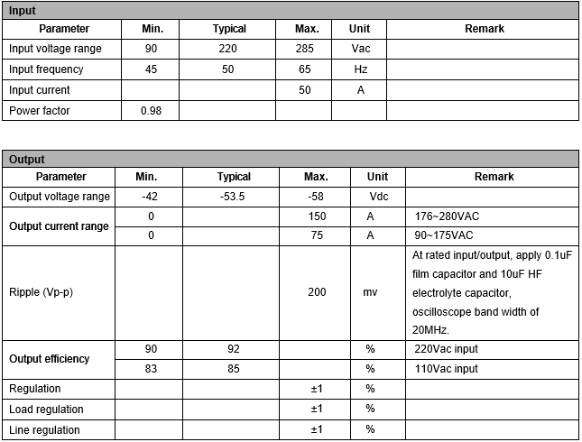
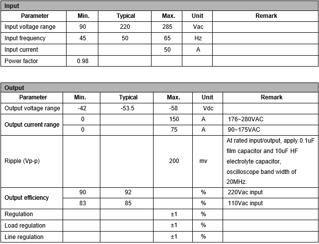
5.1 Properties
|
Item |
Unit |
Min. |
Typical |
Max. |
Testing conditions |
|
AC Input Voltage |
Vac |
90 |
220 |
280 |
|
|
AC input voltage frequency |
Hz |
45 |
50 |
65 |
Rated load |
|
Input power factor |
|
0.99 |
|
|
Rated voltage/rated load |
|
Output voltage range |
Vdc |
42 |
54 |
58 |
|
|
Output current |
A |
0 |
30 |
|
176~290V AC input |
|
Output voltage regulation |
|
|
|
±1% |
|
|
Peak-peak value Vp-p |
mV |
|
|
200 |
Tested with each of 0.1uF ceramic capacitor and 10uF electrolytic capacitor with 20MHz band width. |
|
Output power |
W |
0 |
1600 |
|
176~280V input |
|
W |
0 |
800 |
|
90~175V input |
|
|
Output efficiency |
% |
91 |
|
|
220V AC input |
|
% |
83 |
|
|
110V AC input |
|
|
Input over voltage protection |
Vdc |
285 |
305 |
|
With 15A testing, automatically recoverable |
|
Input over voltage protection recovery point |
Vdc |
280 |
|
|
Return difference not less than 5V |
|
Input under voltage protection |
Vdc |
|
|
85 |
With 4A testing, automatically recoverable |
|
Input under voltage protection recovery point |
Vdc |
|
|
90 |
Return difference not less than 5V |
|
Output over voltage protection point |
V |
58.5 |
59 |
61.5 |
locked up
|
|
Output current limiting protection |
A |
32 |
33 |
34 |
Automatically recoverable |
|
Short circuit protection |
A |
long-term short circuit is available; Hiccup when short circuit detected, automatically recoverable. |
|||
|
Over temperature protection |
|
Automatically recoverable under 65°C ambient temperature |
|||
|
The detailed information is listed in “GPR4830A1 rectifier specification”. |
|||||